
Shelly PLUS 1 quick install

Updated 2023-05-03 !
In a former post I made a writing about Shelly 1(S1) and this post will handle about the successor Shelly PLUS 1(SP1) but much of the content is also valid for some of Shellys other devices which uses the same software/API.
To keep it simple, SP1 is a WiFi switch, 16 Amps, with dry contacts but compared to the S1 the hardware and the software is updated.
The function "without Internet" + that the SP1 can use a 12V DC source makes it perfect for an "use case" in a boat/mobile home.
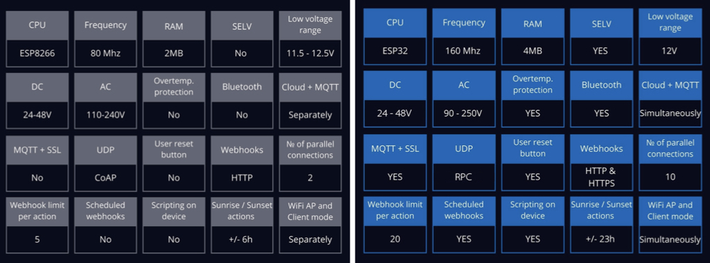
Compare S1/SP1
|
| Shelly 1 versus Shelly PLUS 1 |
The SP1 can also be used to measure temperatures with this add on. With a great software package pre installed You probably don't need anything more, but since it is an ESP32 You can also flash it with Your own/other software.
It's compatible with Alexa, Google or HomeKit using HomeBridge(with plugin) or as a "native" HomeKit device using Mongoose firmware.
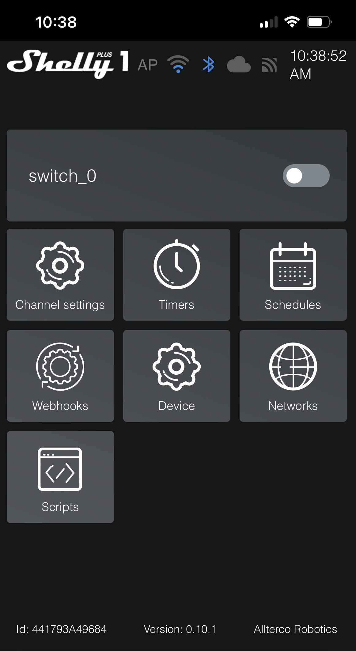
Shelly app
Link to the Shelly apps and the user manual where You will learn about the basic functions.
Installing a SP1
App way
The simple way is using the Shelly app. Register an account at Shelly and then connect S1 to a
powersupply. Then "Settings => Add device => Choose
Wifi-network(your local network, name and password) => Next
=>
Then use one of the 4 methods to include the device
- Select from list
- INCLUDE ANY
- SCAN BY BARCODE (The barcode on the package)
- SEARCH BY BLUETOOTH
and accept the "join" to Your network => Discovered devices =>
Add device => Set name and room/image for device =>
Done". Then You continue with connecting to the cloud.
Go on clicking on the device and then check if there is a firmware update
Go on clicking on the device and then check if there is a firmware update
If you have problem setting up SP1, with the app, check the WEB-server way.
WEB-server way
Another way !!!! to use this function is setting up an HTTP end node, for example in Node Red(NR), which is monitoring the change in the switch.
Cloud API
Accessing the Shelly cloud API is described here
Support
WEB-server way
- Power up SP1 by connecting L and N to mains/power supply
- At first startup SP1 will create its own WiFi, access point, with SSID "ShellyPlus1-nn". nn => individual serial number.
- Connect a device with WEB-browser to the WiFi SSID "ShellyPlus1-nn"
- In the browser, use IP 192.168.33.1, or hostname "ShellyPlus1-nn" for the Shelly web interface
- Select "Networks =>WiFi => Enable => Click here to select network" to add to an existing network
- Use Your local Wifi password
- Optional is static IP address
- Click "Apply" which will confirm "Connected Local_WiFi/192.168.1.nn"
- Connect Your WEB-browser device to the same WiFi
- Access the SP1 with its hostname "ShellyPlus1-nn" or the assigned IP On linux use "arp -e"/Mac "arp -al" to check or the router device list
- With an Internet connection, Device => Firmware version => Check for update, YES (then wait…)
- Disable the access point "Networks => Access point => Enable => Apply"
Now the basic setup is done.
SP1 hardware
The switch
The SP1 pinout is shown in the picture above
Wiring
Shelly software
SP1 hardware
The switch
The SP1 pinout is shown in the picture above
Wiring
Here You find wiring/connection diagrams. You have to create an account on the support site.
External switch
And don't miss that You via "Channel Settings" can change the behavior of the connected external switch
External switch
And don't miss that You via "Channel Settings" can change the behavior of the connected external switch
Built in WEB-server
You don't even have to have the devices connected to Your WiFi because, check "WEB-server way" above, they have their own built in WEB-server which, at first start up, creates its own WiFi acting as an Access point.Factory reset can be done by one of the following methods
- Reset button
- Push the reset button, on the rear side of the SP1, for 10 seconds
- External Switch
- Restore power.
- Within the first minute, toggle a switch connected to the "SW" input on the Shelly 5 times on/off (10 total) or press and release momentary button 5 times.
- The Shelly relay should click rapidly and the device will be reset to factory settings.
- Shelly app
- Select the device
- Settings => Factory reset
- WEB interface
- Device => Factory reset
RPC Protocol
Documentation
Documentation
The API documentation is found here and you can communicate through several channels. I will show some examples, for the HTTP GET request, which maybe
will make Your start easier for the Switch component.
Check status
For example to check the switch status use. (The URL can be used in a ordinary browser)
For example to check the switch status use. (The URL can be used in a ordinary browser)
http://ShellyPlus1-44179AA49684/rpc/Switch.GetStatus?id=0
where "44179AA49684" should be substituted with Your serial number for the actual device.
Another way could be using the device IP adress which shall substitute
"ShellyPlus1-44179AA49684". The request will return a JSON answer specified here.
{
"id": 0,
"source": "WS_in",
"output": false,
"temperature": {
"tC": 56.6,
"tF": 133.9
}
}
The ""output": false" shows that the relay is turned off, otherwise the state would have been "true".
Turn switch/relay on/off
To turn on the relay use
http://ShellyPlus1-44179AA49684/rpc/Switch.Set?id=0&on=true
With response
With response
{
"was_on": true
}
which tells us that the relay already was turned on.
The "0" is the channel, which in this case with a S1 could just
be "0" because You just have one relay. Other products may have several
channels.
MQTT
How to is described here
Webhooks
This means that each device can communicate with another one without a server or cloud connection. The possible conditions to monitor can be retrieved with
How to is described here
This means that each device can communicate with another one without a server or cloud connection. The possible conditions to monitor can be retrieved with
http://ShellyPlus1-44179AA49684/rpc/Webhook.ListSupported
Use the app or WEB interface to check and set the 2 conditions/URLs so that when one SP1 turns off another one shall be turned on
Set "device_1" to;
Webhooks => Add webhook =>
Set name => off
Condition => When switch is Off
URL => http://device_2/rpc/Switch.Set?id=0&on=true
Set name => on
Condition => When switch is On
URL => http://device_2/rpc/Switch.Set?id=0&on=false
Another way !!!! to use this function is setting up an HTTP end node, for example in Node Red(NR), which is monitoring the change in the switch.
With;
Webhooks => Add webhook =>
Set name => off
Condition => When switch is Off
URL => http://home:1880/shelly/0
Set name => on
Condition => When switch is On
URL => http://home:1880/shelly/1
You will get an "1" for switching ON respective "0" for OFF.
On the NR server "home" set up an http end node =>
Method => GET
URL => /shelly/:sts
and then a function node with code
msg.payload = parseInt(msg.req.params.sts);
return msg;
followed by a http response node.
A similar example is shown here.
Cloud API
Accessing the Shelly cloud API is described here
Support
The Shelly support WEB-page


Comments
If used together with momentary push button with led ribg light in my switch panel at helm stations, do you think two Shelly, one at each helm for each device controlled, could work in parallel?
UseCase; At helm station A (all devices are wirred to), turning on ex. anchor light the push button led ring light also turns on, indicating the anchor light are on. At helm station B (no devices are wirred to helm station B, but the Shelly parallel with the shelly at helm stationA), the push button ring light turns on
Post a Comment
Feel free to leave a comment ! ... but due to a lot of spam comments I have to moderate them. Will reply ASAP !