
SeaTalk1 to NMEA 0183 converter, DIY

Updated 2024-08-30 !
!! Another SW solution is available for RPi 5 here ! using the same HW.
Thanks to Thomas, (the guy with the nice marine interface board), it's now possible to decode, one way, the SeaTalk1(ST1) sentences in a pretty simple way.
You just use
OpenPlotter(OP)
and/or SignalK(SK) and
an Optocoupler.
The thing that made it, is that Thomas has released a "how to" and Python source code,
that will read the data from a GPIO pin on the Raspberry Pi, (RPi), and
format it so the
standard parser in SignalK
can translate it to SignalK delta format. It is then available as NMEA 0183. It's even possible to send the data in to a
NMEA 2000 network, with a proper hardware interface.
Hardware

The circuit is referring to this optocoupler board, but a similar product can of course be used. The LED in the circuit will flicker when there is ST1 traffic. Choosing an optocoupler as the hardware interface is a smart way to avoid ground loops and creates electrical isolation from hazardous voltages. This interface is not inverting the signal.

If you are building the interface yourself use the second circuit instead. If you don't want any flickering just drop the LED at the input.
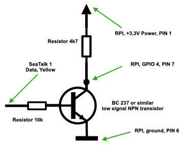 The most simple interface, works well on our boat, is where You use a small signal NPN transistor which shifts the DC level, from 12 V DC to 3,3 V DC, and inverts the signal.
Software
Install
Start, in a terminal/ssh session, with an update and install
sudo apt-get update && sudo apt-get install pigpio python-pigpio python3-pigpio
pigpiod -v
79
wget
https://raw.githubusercontent.com/MatsA/seatalk1-to-NMEA0183/master/STALK_read.py
The program is set up to match the opto circuit above.
pigpio
The Python program is dependent on that the "pigpio" library is launched as a demon. Start it with
sudo pigpiod Which starts a socket interface on port 8888 !! which is used by the Python
program.
then start the program with
sudo python STALK_read.py
STALK,11,1,4,5
STALK,25,4,e8,51,12,33,3
STALK,24,2,0,0,20
STALK,26,4,0,0,0,0,20
STALK,9c,31,13,fe
showing the decoded ST1 messages. Next step is to check that the messages is sent out as an UDP stream at local host, port 4141. This is done with opening a new terminal/ssh session and issue the commandnc -ulkw 0 127.0.0.1 4041
and the same list of ST1 messages will appear. Terminate with "Ctrl +
c".
SignalK
Connection
To get the ST1 messages into SignalK, using the optocoupler setup, You have to set up a new
connection in SignalK. Setup according to the picture below. After
restarting SK, check out the ST1 messages in the "Data
Browser".


sudo killall pigpiod
Prepare for "production"
Move the Python program to a better place
systemd service
We will set up "STALK_read.py" as a systemd service, autostart at boot and restart at failure, which also will start
the "pigpio" daemon. Get the service file
sudo mv SeaTalk.service /etc/systemd/system
then activate it with
Check ST 1 messages
Check with sudo systemctl status SeaTalk
and something like this will be listed
sudo systemctl status SeaTalk
●
SeaTalk.service - SeaTalk daemon
Loaded:
loaded (/etc/systemd/system/SeaTalk.service; enabled; vendor preset:
enabled)
Active: active (running)
since Sun 2020-06-14 11:04:50 CEST; 44s ago
Docs:
http://pysselilivet.blogspot.com/2020/06/seatalk1-to-nmea-0183-converter-diy.html
Process: 534
ExecStartPre=/usr/local/bin/pigpiod (code=exited,
status=0/SUCCESS)
Main PID: 544
(python)
Tasks: 8
(limit: 4035)
Memory:
7.1M
CGroup:
/system.slice/SeaTalk.service
├─539 /usr/local/bin/pigpiod
└─544 /usr/bin/python /usr/local/sbin/STALK_read.py
Jun 14 11:05:29 zest SeaTalk[544]: $STALK,9c,31,18,ff
Jun 14 11:05:29 zest SeaTalk[544]: $STALK,57,70,2
Jun 14 11:05:29 zest SeaTalk[544]:
$STALK,58,25,38,1b,64,c,8d,d0
Jun 14 11:05:29 zest SeaTalk[544]:
$STALK,84,36,98,88,40,0,ff,2,17
Jun 14 11:05:29 zest SeaTalk[544]: $STALK,25,4,e8,51,12,33,3
Jun 14 11:05:29 zest SeaTalk[544]: $STALK,24,2,0,0,20
Jun 14 11:05:29 zest SeaTalk[544]: $STALK,26,4,0,0,0,0,20
Jun 14 11:05:29 zest SeaTalk[544]: $STALK,20,1,0,0
and then check the ST1 messages in "Data Browser".
If You don't want to clutter Your log with the ST1 sentences, just edit
the Python code
and make the "print (data)" line start with an "#" and reactivate the service with the
above commands.
Now You are ready for "production" !
Remarks
Change port
If You want to change the daemon to another port You have to
change the pigpiod.service file with the -p option, and the
Python program.
Signal K
Please note ! With help
from @tkurki I added this conversion feature to the standard SK server, V1.32. Documentation
found here.
Open plotter
This setup will soon be added to the documentation but in the meantime please check this post in the OP forum.
Fixes
2020-08-18 The "STALK_read.py" program is updated with 2 bug fixes !! These are also applied to the SK
server version.
2021-02-18 The "STALK_read.py" updated.
2022-11-03 SeaTalk.service updated.
2023-07-29 Hardware interface updated at input to the optocoupler board.
WiFi converter
Why don't use the above setup with a
Raspberry Zero W, with the one transistor interface, to get ST1 input, via WiFi, to Your
SK server ?
Hardware tuning
The mentioned hardware solution worked in my environment but Marco have done a deeper analyze, with an oscilloscope, which can be checked out here. This post update, done 2023-07-29, is taken that info in consideration.


Comments
PID USER PR NI VIRT RES SHR S %CPU %MEM TIME+ COMMAND
700 root 20 0 21500 8236 5620 S 77.8 0.9 5:01.99 python
492 root 20 0 12480 1616 1416 S 43.4 0.2 5:00.66 pigpiod
thinking of getting this output separately from the other seatalk instruments. Putting two pi's at the helm station seems overkill, but would be nice if I could use one pi to read both.
any ideas?
I'm desperate about making the Seatalk work on my Raspberry, so may be someone here will have an idea about what is wrong.
I have build the optocoupler interface described at https://github.com/SignalK/signalk-server/blob/master/Seatalk(GPIO).md
(same as yours)
with a similar optocoupler circuit. I measured with an ohmmeter the resistances on the optocoupler board and they are 3K as well.
I have at least 4 Seatalk instruments daisy-chained with official cables. On one of the cable there is a splice that connect to the autopilot course computer ST100/300 where I took out the Seatalk input signal to the Optocoupler.I also tried to connect the optocoupler directly to another instrument ST output, with the same results.
I connected the circuit with a 4660 Ohm resistor to a Raspberry Pi zero W (headless, running Signalk server) and created the connection as describer in Github (GPIO 4 / inverted).
I have no signal in Signalk, nor with the tool STALK_read.p.
Then I measured the voltage (with a voltmeter, I don't have an osciloscope) at the Seatalk connector (with the optocoupler disconnected): I can see a fluctuating voltage between 11V and 12V so I conclueded that that was actually ST data (plus as the autopilot ST100/300 works fine, I guess it can be concluded that it receives correct ST data).
Then I measured the voltage when the optcouper is connected at the same point: I can see fluctuating voltage around 5V to 6V.
Then I measured the voltage at the GPIO pin and could see a fluctuating voltage of 1.5-1.7 V.
So I imagined that for some reason, the voltage at the GPIO was not suffisant to pull the signal down (I've read somewhere on line that you need at least 1.8V to change GPIO inputs). So I replaced the 4660 resistor with 4000, then 3000 to see what happens. With 3000 the STALK_read.p started to display STALK messages (that I'm unable to decode) and the SIgnalK server started to show only 2 data (Magnetic deviation and depth). Nothing else (on top of that the only instrument which is not connected is the depth sounder ;-), so it looks to me as garbage.
I tried to remove the invert setting but it didn't change anything (Is there a possibility that I burnt the GPIO doing that?).
- Is the optocoupler functioning correctly? (I tried another one from the same batch with same results). Why haven't I fluctuating 12V at the input?
- Is the Raspberry pi zero fast enought to decode the ST data flow ? (I believe 4.8 kbauds is not that fast for a pi zero.
Any help welcome!
Not sure if anyone is monitoring this.
I have a bunch of $STALK sentences, but how can I convert them into readable NMEA0183 sentences like $IIMTW - water temp $IIDBT - depth, etc.
Thanks
It's easy to make all the seatalk equipment connected to raspberry pi and make it much way easier, also the good thing when using raspberry pi you can do a logger and that you can have all the data in charts or anything like that
Post a Comment
Feel free to leave a comment ! ... but due to a lot of spam comments I have to moderate them. Will reply ASAP !